Проектирование систем напольного и настенного поверхностного отопления: различия между версиями
(Новая страница: «<IS_HELP id="HS47"/> {{Article table |commercial_product1=InstalSystem 5 |p2 =<!--gdy jest kolejny produkt handlowy, zamienić na->"produkt_handlo...») |
м (Klintsevicho переименовал страницу New article в Проектирование систем напольного и настенного поверхностного отопления) |
(нет различий)
| |
Версия от 09:31, 28 марта 2022
| Продукция | InstalSystem 5 |
| Тип статьи | DESIGNING LESSON |
| Дата перевода | 2022-02-23 |
Scope of lesson
This article presents the method of designing radiant heating systems in loop arrangements (dry and wet).
The example shown is based on a design for a single-family two-storey house with no basement.
Modules and program configuration
The InstalSystem 5 includes the following module:
- Системы поверхностного отопления.
Webinars
We encourage you to see the video from our webinars on the topics described in this article:
The webinars present the topics described in this article, but they aren’t a recording of this lesson.
Inital state
The project includes a complete set of default data defined in a template.
The rooms arangement was based on base drawings in DWG format. More details in: Table of project example.
Steps to perform
Open new project file
- Launch InstalSystem 5.
- Open a new project and choose the preferred file version.
Более подробную информацию см.: Project and application management - Select the appropriate template.
Более подробную информацию см.: Template files
Define catalogues and general data
Declare Общие данные in default data:
- Управление этажами - add the required number of storeys
Более подробную информацию см.: Preparation of building structure - Обслуживание каталогов - choose catalogues according to the list in the Project table with regard to:
- Поверхностные системы
- Трубы и фитинги
- Изоляция
- Клапаны и арматура
- Система отопления/охлаждения - append information for:
- Система труб
- Типы и данные по умолчанию
- Поверхностные системы
- Напольная система
- Настенная система
- Коллекторы и автоматика
- Система труб
Более подробную информацию см.: Using catalogs and catalogs data in the project
| Файлы проекта
|
Floor and wall radiant heating system in single-family house, isproj |
| Разработано с | InstalSystem 5 Rev. Beta 30 |
| Требуемые модули | Базовый модуль Системы отопления Системы поверхностного отопления |
| Диапазон проектов | Radiant heating |
| Используемые каталоги |
Basic radiant systems |
| Тип здания | single-family no basement 2-storey |
| Строительная конструкция | Base drawing ground floor, dwg Base drawing first floor, dwg |
| Диапазон чертежей | Plan view |
| Подготовлено |  www.instalsoft.com |
| Правовая информация | Copying of entire project and of its fragments allowed |
| Результаты расчетов | Full printout, xls Full printout, pdf Radiant heating calculation results, pdf Bill of materials, pdf Installation parameters, pdf |
| Итоговые чертежи | Ground floor, dwg First floor, dwg Ground floor, pdf First floor, pdf |
Prepare building structure
- Import, rescale and arrange in relation to each other, by inserting Точка отсчета, base drawings for each storey.
Более подробную информацию см.: Import files - Redraw rooms in the rescaled base drawing using the АВТО mode.
Более подробную информацию см.: Insert rooms - Automatically number the rooms using the Пронумеровать помещения function. Start from the room in the upper left corner of each storey.
- Make appropriate corrections in Таблица данных:
- Design temperature: enter 24°C for bathrooms, 16°C for lobby.
- Maximum permissible floor surface temperature by selecting appropriate room type in the Отопление section.
- For unheated rooms, specify the value of heat loss index as "0".
Более подробную информацию см.: Setting up the building structure
- Verify the correctness of the structure entered in 3D вид.
Более подробную информацию см.: Preparation of building structure
Edit installation - radiant system
Нагр./Охл. зона
- Insert Нагр./Охл. зона components in selected rooms.
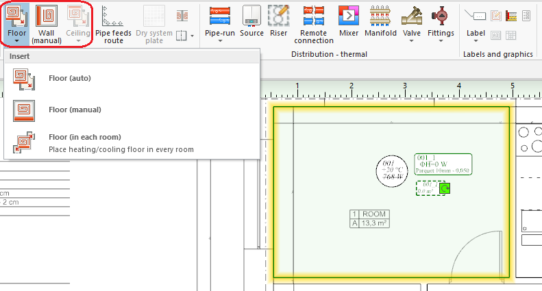
1. Inserting Нагр./Охл. зона - Cut out appropriate fragments of: Нагр./Охл. зона and/or change their shapes to adapt them to occupied areas (stairs, bathtubs) in rooms.
- Divide selected areas of Нагр./Охл. зона with regard to required expansion allowances.
- Declare and set up the Граничная зона (ГЗ).
Более подробную информацию см.: Dividing a Heating/Cooling Zone

Распределитель
- Insert Распределитель on every storey. Распределитель is inserted in the drawing together with manifold cabinet.
Более подробную информацию см.: Manifolds for radiant system and their accessories

Трассировка трубопроводов
- Connect Нагр./Охл. зона with manifolds using Трассировка трубопроводов. Трассировка трубопроводов enables automatic generation of pipe feeds.
Более подробную информацию см.: Editing pipe feeds in a radiant system

Edit installation - feed to manifolds
Источник
- Insert Источник on the lowermost storey.
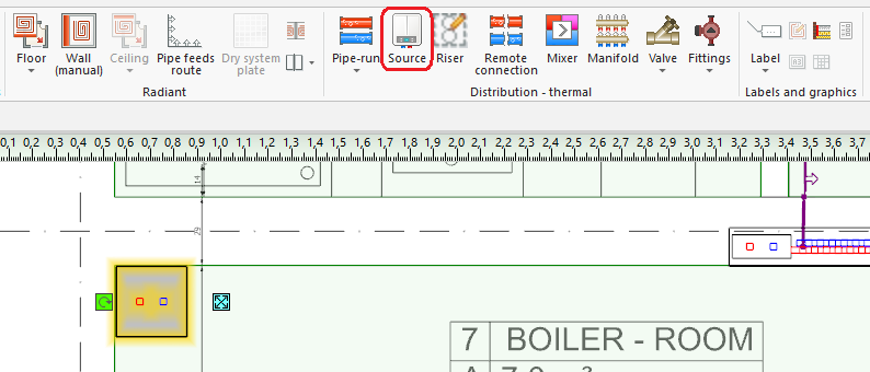
4. Inserting Источник

Стояк
- Insert Стояк, assign a symbol to it and define its extent (from storey 0 to storey 1).
Более подробную информацию см.: Connecting storeys with the "Stack" element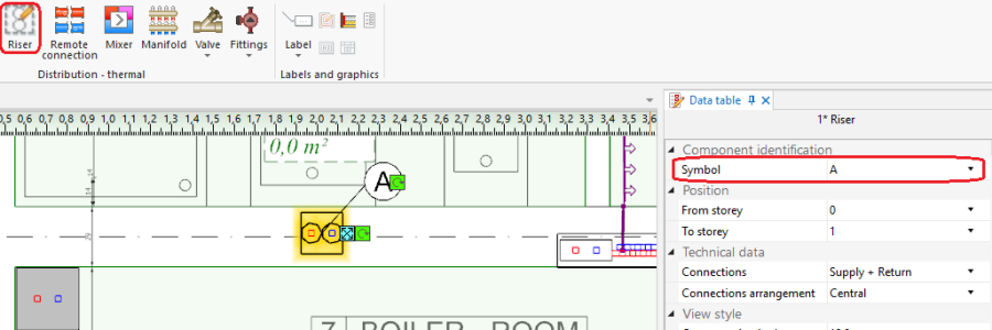
5. Inserting Стояк

Distribution
- Connect Источник, Распределитель, Стояк with each other by drawing the network using the Участок component and the АВТО and ОРТО modes.
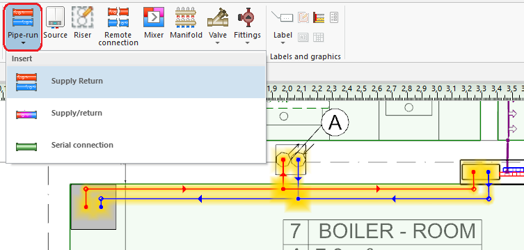
6. Connecting system components

Fittings
- Insert Клапан onto pipe-runs.
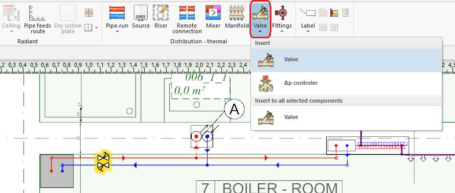
7. Inserting Fittings - Select Тип клапана in Таблица данных.
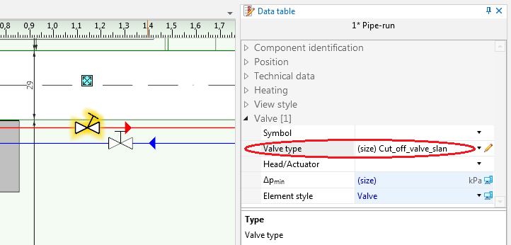
8. Тип клапана - Use Copy - Paste to insert fittings of the same type onto other pipe-runs.


Verify correctness of installation structure
- Verify the correctness of the installation structure using the Проверить соединения function (Key shortcut: Shift + F2).
- Verify the correctness of the installation structure and find conflicts using 3D вид.
Более подробную информацию см.: Verification of the correctness of installation structure
Edit installation components data
Покрытие
- Mark selected Нагр./Охл. зона components and specify the type of Покрытие.
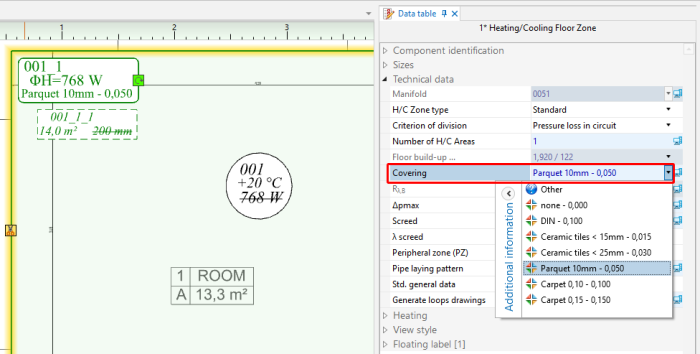
9. Покрытие

Нагр./Охл. зона
- Mark these Нагр./Охл. зонаs where significant surface area is occupied by pipe feeds and change their type to Отапливаемая/охлаждаемая подводами. Remember in this case to remove connections with the manifold.
- Mark these Нагр./Охл. зонаs where no loops are to be arranged and change their type to Без труб.
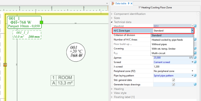
10. Type Нагр./Охл. зона

Calculations and diagnostics
Radiant system calculations
- Launch complete calculations by clicking the
 icon in the Расчёт section of the toolbar.
 - Open the Диагностика window by selecting it in the list of windows or by pressing F8.
- After calculations are completed verify the messages listed in the Диагностика window. If error messages are displayed, these must be eliminated in the first place.

Более подробную информацию см.: Calculations and diagnostics
Modifying system parameters to adapt attained output to required output
- Change feed temperature of the radiant system by using control circuits, which can be found in Общие данные window in Система отопления/охлаждения/Источники section.
Более подробную информацию см.: Interactive calculations of radiant systems

- Change pipe spacing and temperature drop in individual loops.
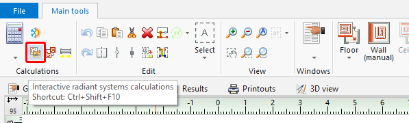
12. Интерактивный расчет системы


- Change structure of heating floor\wall.
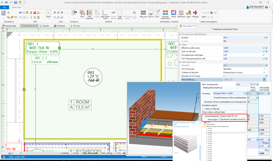
14. Констр.пола ... - Change Макс. потери давл. в кольце.
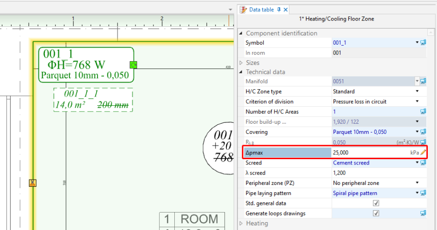
15. Макс. потери давл. в кольце


Modifying the dividing line of element Нагр./Охл. зона to elements Нагр./Охл. поверхность
Более подробную информацию см.: Modifying the dividing line after automatic division
Manual correction of automatically generated pipe feeds route
Более подробную информацию см.: Трассировка трубопроводов - manual correction of automatically generated pipe feeds route
Appending drawings with radiant system loops
Более подробную информацию см.: Appending drawings with radiant system loops
Including of drawing loop lenght in the calculations
Более подробную информацию см.: How to include the drawing loop lenght in the calculations?
Using of plates in dry floor heating system
Более подробную информацию см.: Inserting plates in dry floor heating system
Recalculation and verification of results
- Verify calculation results paying special attention to:
- coverage of heat demand in rooms,
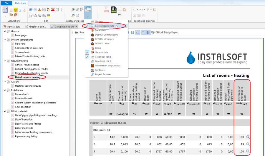
16. Покрытие требуемой мощн.отопления - sized layers in Пол с подогревом и охлаждением, to see if there are no undesirable differences in height/thickness in adjacent areas.
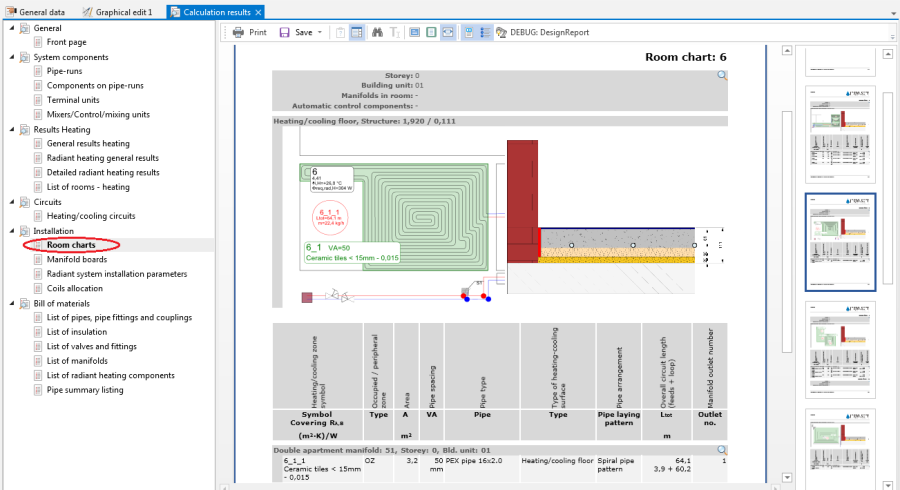
17. Констр.пола ... - bills of materials.
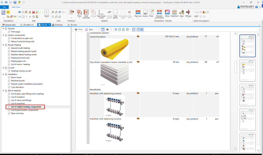
18. Спецификация материалов - Нагр./Охл. - Список элементов П.О.
- coverage of heat demand in rooms,


Prepare drawing for printing/export
Метка
- Insert required labels onto components.
- Configure the label appearance (opc).
Более подробную информацию см.: Item 5. Component appearance configuration and editing parameters configuration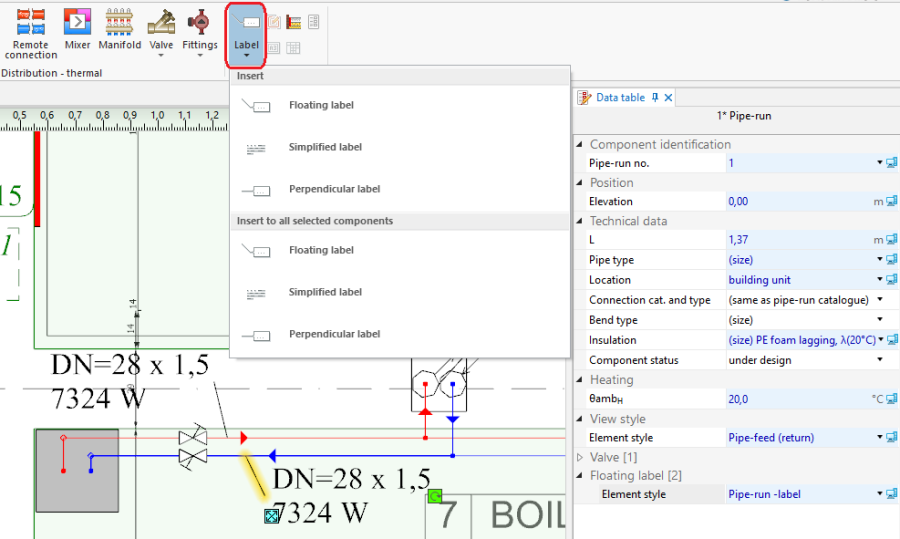
19. Inserting Метка

Таблица распределителя
- Insert Таблица распределителя.
Более подробную информацию см.: Manifold label and table
Узел конструкции теплого пола
- Insert Узел конструкции теплого пола. Rescale and configure, if necessary.
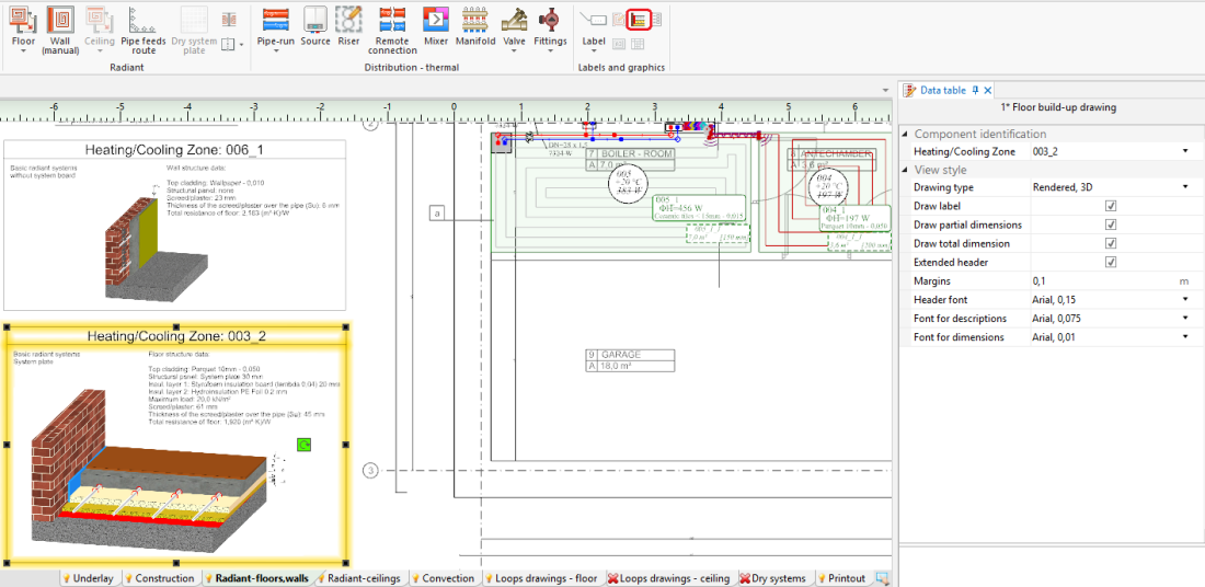
20. Узел конструкции теплого пола

Петля RHC
- Automatically generate the Петля RHC drawings.
Более подробную информацию см.: Automatic generation of loop drawings - Check the generated Петля RHC drawings and modify them manually, if necessary.
Более подробную информацию см.: Manual editing of loop drawings
Формат бумаги
- Insert Формат бумаги.
- Select Формат бумаги in Таблица данных .
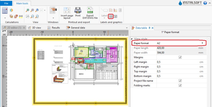
21. Inserting Формат бумаги

Таблица проекта
- Insert Таблица проекта.
- Enter the required data in Таблица данных.
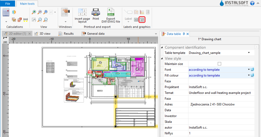
22.Таблица проекта

Print/export results
- Print/export drawings.
- Print/export tables.
Более подробную информацию см.: Export / print results and drawings